
Deployment Architecture
Introduction
Each topology is shown as a diagram followed by a component table. The identification numbers in the diagram match the numbers in the table.
Recommended environments
Separate TEST, UAT, and PROD environments are recommended. TEST and UAT can share some infrastructure, but each needs its own IIS sites, Reserves Agent services, databases, and Azure Service Bus namespaces.
About the diagrams
- Scope: The diagrams show Reserves components and how they connect. They are not network diagrams, and the only ports shown are those for Azure Service Bus.
- Firewalls: Firewalls are not shown, but are recommended for any enterprise application in a corporate environment.
- Connections: The topology diagrams show how components are deployed. Every validated connection, with its protocol and port, is shown in the topic Minimum Requirements ('Connection details' sub-section under 'Ports and protocols').
- Arrows: Arrows show communication between components. They do not indicate firewall rule direction.
- Planning Space integration: This integration is optional and appears only where Planning Space is deployed alongside Reserves. The Planning Space databases are shown for deployment context only, because Reserves does not connect to them.
- High availability: Where high availability is required, the diagrams show the minimum number of servers needed to achieve it. High availability using an on-premises Microsoft SQL Server is not shown.
- Disaster recovery: This is not covered in this topic and DR components do not appear in the diagrams.
Standard and advanced topologies
- Standard: The Web and Reserves Agent services run on one server.
- Advanced: The Reserves Web Server and Reserves Agent run on separate servers, with optional load balancing and clustering. This topology should be used when high availability or additional capacity is required.
On-premises hybrid
Standard
The Web and Reserves Agent services run on the same server.
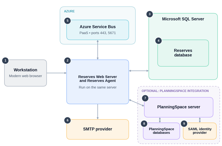
Arrows show communication between components. Dashed outlines mark optional integrations. Numbers match the component descriptions in the following table.
| Number | Component | Description |
|---|---|---|
| 1 | Workstation | User computer with a modern web browser, used to access Reserves |
| 2 | Reserves Web Server and Reserves Agent | The Reserves web application and the Reserves Agent running on the same server. |
| 3 | Microsoft SQL Server | Hosts the Reserves database. |
| 4 | Reserves database | Application schema and data. |
| 5 | Azure Service Bus | PaaS messaging service. See topic Minimum Requirements (sub-section 'Connectivity' under 'Azure Service Bus') for port information. |
| 6 | SMTP provider | SMTP server used to send email from Reserves. |
| 7 | Planning Space server | (OPTIONAL) Used for authentication and licensing when Planning Space is integrated with Reserves. |
| 8 | Planning Space databases | Common (system) and tenant databases used by Planning Space. |
| 9 | SAML identity provider | Can be used for authentication via the Planning Space server when Planning Space is integrated with Reserves. |
Advanced
The Web and Reserves Agent services can run on separate servers. Load balancing and clustering are optional, to support high availability and additional capacity.
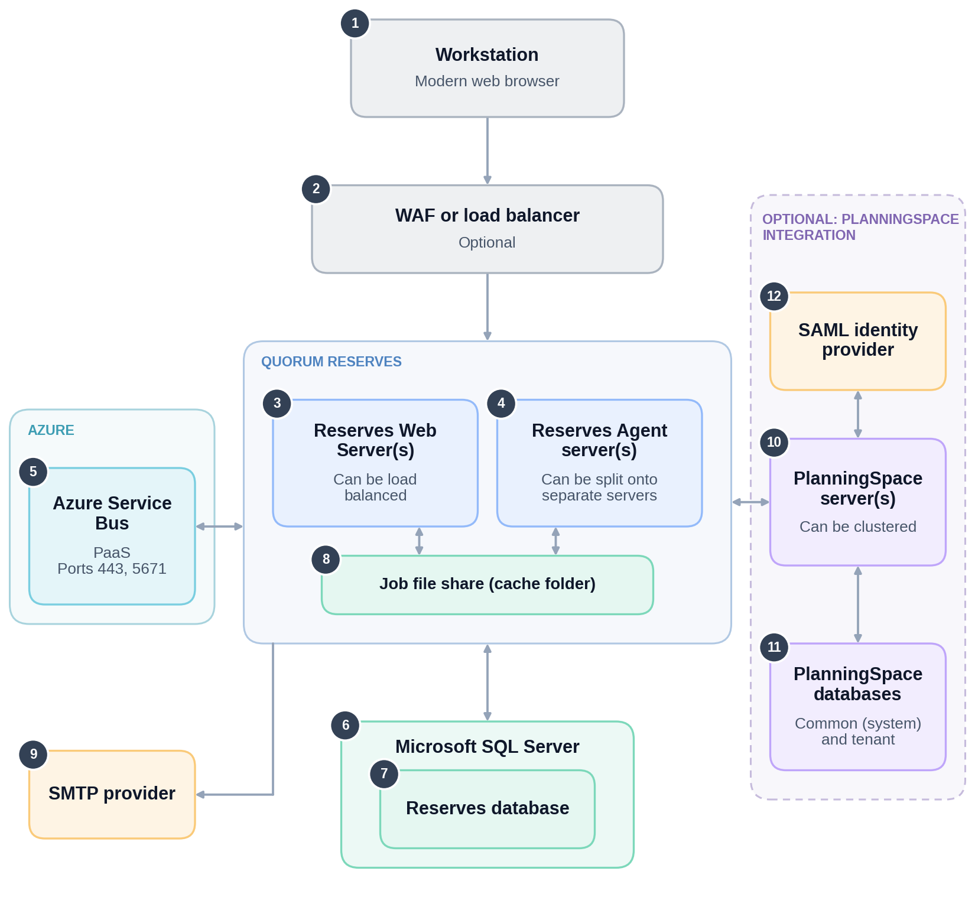
Arrows show communication between components. Dashed outlines mark optional integrations. Numbers match the component descriptions in the following table.
| Number | Component | Description |
|---|---|---|
| 1 | Workstation | User computer with a modern web browser, used to access Reserves. |
| 2 | WAF or load balancer | (OPTIONAL) Distributes browser traffic across multiple Reserves Web Servers to allow high availability of the application. |
| 3 | Reserves Web Server(s) | Can be load-balanced for high availability. |
| 4 | Reserves Agent server(s) | Can be deployed as multiple servers for additional capacity and/or high availability. |
| 5 | Azure Service Bus | PaaS messaging service. See the topic Minimum Requirements (sub-section 'Connectivity' under 'Azure Service Bus') for port information. |
| 6 | Microsoft SQL Server | Hosts the Reserves database. |
| 7 | Reserves database | Application schema and data. |
| 8 | Job File Share (cache folder) | Holds jobs created by the Reserves Web Server(s) for pickup by the Reserves Agent(s). |
| 9 | SMTP provider | SMTP server used to send email from Reserves. |
| 10 | Planning Space server(s) | (OPTIONAL) Can be clustered for high availability. Used for authentication and licensing where Planning Space is integrated with Reserves. |
| 11 | Planning Space databases | Planning Space common (system) and tenant databases. |
| 12 | SAML identity provider | Can be used for authentication via the Planning Space server(s) where Planning Space is integrated with Reserves. |
Azure only
Quorum services should be deployed via IaaS in the same region/zone as Azure services.
Standard
The Web and Reserves Agent services run on the same server.
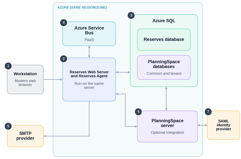
Arrows show communication between components. Numbers match the component descriptions in the following table.
| Number | Component | Description |
|---|---|---|
| 1 | Workstation | User computer with a modern web browser, used to access Reserves |
| 2 | Reserves Web Server and Reserves Agent | The Reserves web application and the Reserves Agent running on the same server. |
| 3 | Azure SQL | Hosts the Reserves database and the Planning Space (common and tenant) databases. |
| 4 | Azure Service Bus | PaaS messaging service. See sub-section 'Connectivity' under 'Azure Service Bus' for port information. |
| 5 | SMTP provider | SMTP server used to send email from Reserves. |
| 6 | Planning Space server | (OPTIONAL) Used for authentication and licensing when Planning Space is integrated with Reserves. |
| 7 | SAML identity provider | Can be used for authentication via the Planning Space server when Planning Space is integrated with Reserves. |
Advanced
The Web and Reserves Agent services can run on separate servers. Load balancing and clustering are optional and support high availability and additional capacity.
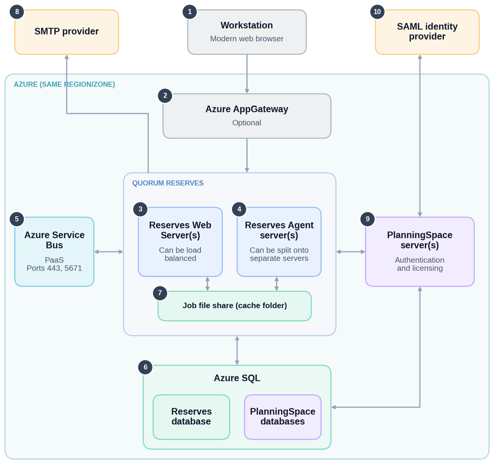
Arrows show communication between components. Numbers match the component descriptions in the following table.
| Number | Component | Description |
|---|---|---|
| 1 | Workstation | User computer with a modern web browser, used to access Reserves. |
| 2 | Azure AppGateway | (OPTIONAL) Distributes browser traffic across multiple Reserves Web Servers to allow high availability of the application. |
| 3 | Reserves Web Server(s) | Can be load-balanced for high availability. |
| 4 | Reserves Agent server(s) | Can be deployed as multiple servers for additional capacity and/or high availability. |
| 5 | Azure Service Bus | PaaS messaging service. See the topic Minimum Requirements (sub-section 'Connectivity' under 'Azure Service Bus') for port information. |
| 6 | Azure SQL | Hosts the Reserves database and the Planning Space (common and tenant) databases. |
| 7 | Job File Share (cache folder) | Holds jobs created by the Reserves Web Server(s) for pickup by the Reserves Agent(s). |
| 8 | SMTP provider | SMTP server used to send email from Reserves. |
| 9 | Planning Space server(s) | (OPTIONAL) Can be clustered for high availability. Used for authentication and licensing where Planning Space is integrated with Reserves. |
| 10 | SAML identity provider | Can be used for authentication via the Planning Space server(s) where Planning Space is integrated with Reserves. |
Job File Share (Cache folder)
The Job File Share, also called the cache folder, holds the jobs that the Reserves Web Server creates for the Reserves Agent to pick up. How it is set up depends on the topology.
Standard topology
The cache folder is a local folder inside the installation directory, by default '{BasePath}\cache\{database}'. The Reserves Web Server and Reserves Agent use the same local folder, and no network share is needed.
No extra configuration is required. The permissions set on the installation directory already cover the cache folder.
Advanced topology
The cache folder is network share, located outside the installation directory of every server. It must be specified as a UNC path, because the Reserves Web Server and Reserves Agent are running on separate servers.
Set up the share following the example given below. In Azure deployment, use a Windows file share. Availability will depend on the customer’s storage, so high availability storage must be used in production.
Example for setting up the file share: This assumes advanced topology is used for a deployment containing two Web Servers ('Web1' and 'Web2').
- On Web1, create a file share on a folder that the application pool service account and the Reserves Agent service account can read and write, for example '\\Web1\cacheshare'.
- In the CCM, enter this share under' QuorumReserves Configurations / Paths / Cache Path'.
- In the CCM, enter the same share under 'Agent Configurations / Path', for both Job Files and Cache Path.